Table of Contents
Key Technical Takeaways
Essential updates implemented in HTS CANBUS 2.3.0 for powertrain calibration and live onboard telemetry analysis:
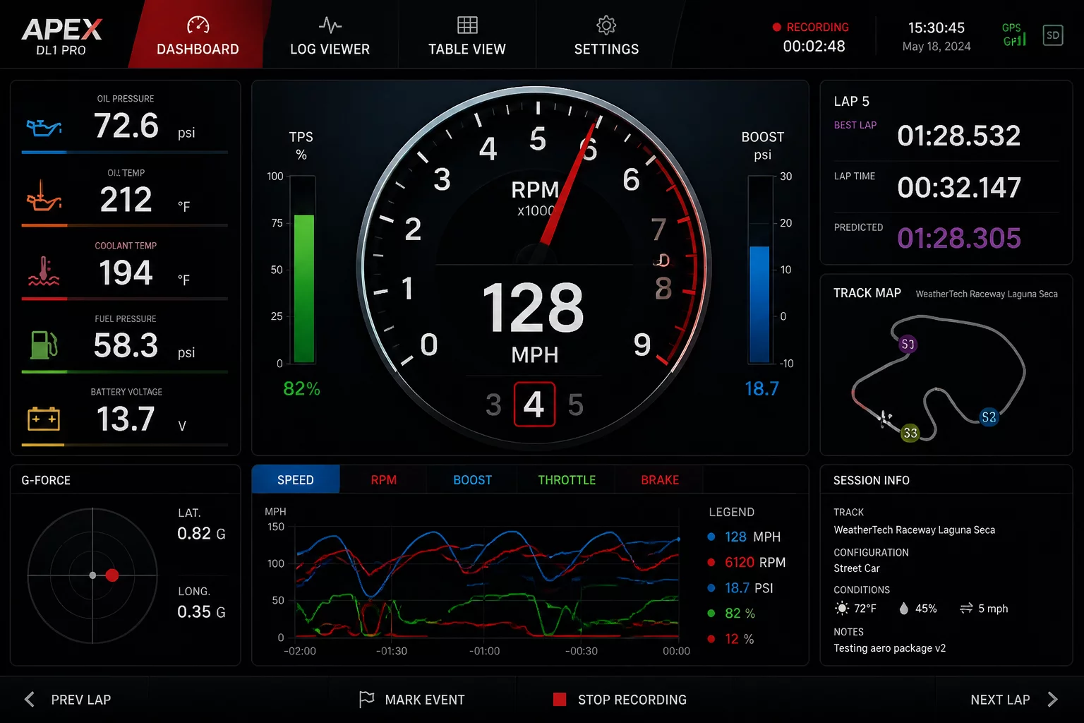
- Enhanced dynamic UI renders high-DPI vector dials and configurable split-view trace charts with zero frame drops during peak CAN bus utilization.
- Optimized multi-frame PID request pipelining achieves sustained 100 Hz polling across up to 64 simultaneous powertrain parameters.
- Integrated ring-buffer management prevents packet dropping during high-load CAN FD burst traffic transmissions.
Architecture Overhaul & Gauge Engine
The core motivation behind HTS CANBUS 2.3.0 centers on telemetry rendering throughput. Previous interface revisions occasionally suffered from graphic thread contention when parsing dense multi-node broadcast messages alongside fast PID polling. Version 2.3.0 isolates the visual gauge rendering engine onto a dedicated hardware-accelerated thread, ensuring fluid 60 FPS dial animations, peak-hold markers, and instant threshold warnings regardless of CPU workload.
Field technicians and calibration specialists can now construct custom cockpit layouts with modular instrument clusters. Whether monitoring boost pressure differentials, closed-loop lambda targets, or transmission fluid line pressures, gauges can be snapped into tiled grids or layered over real-time scrolling wave plots.
High-Speed Telemetry & Trace Buffering
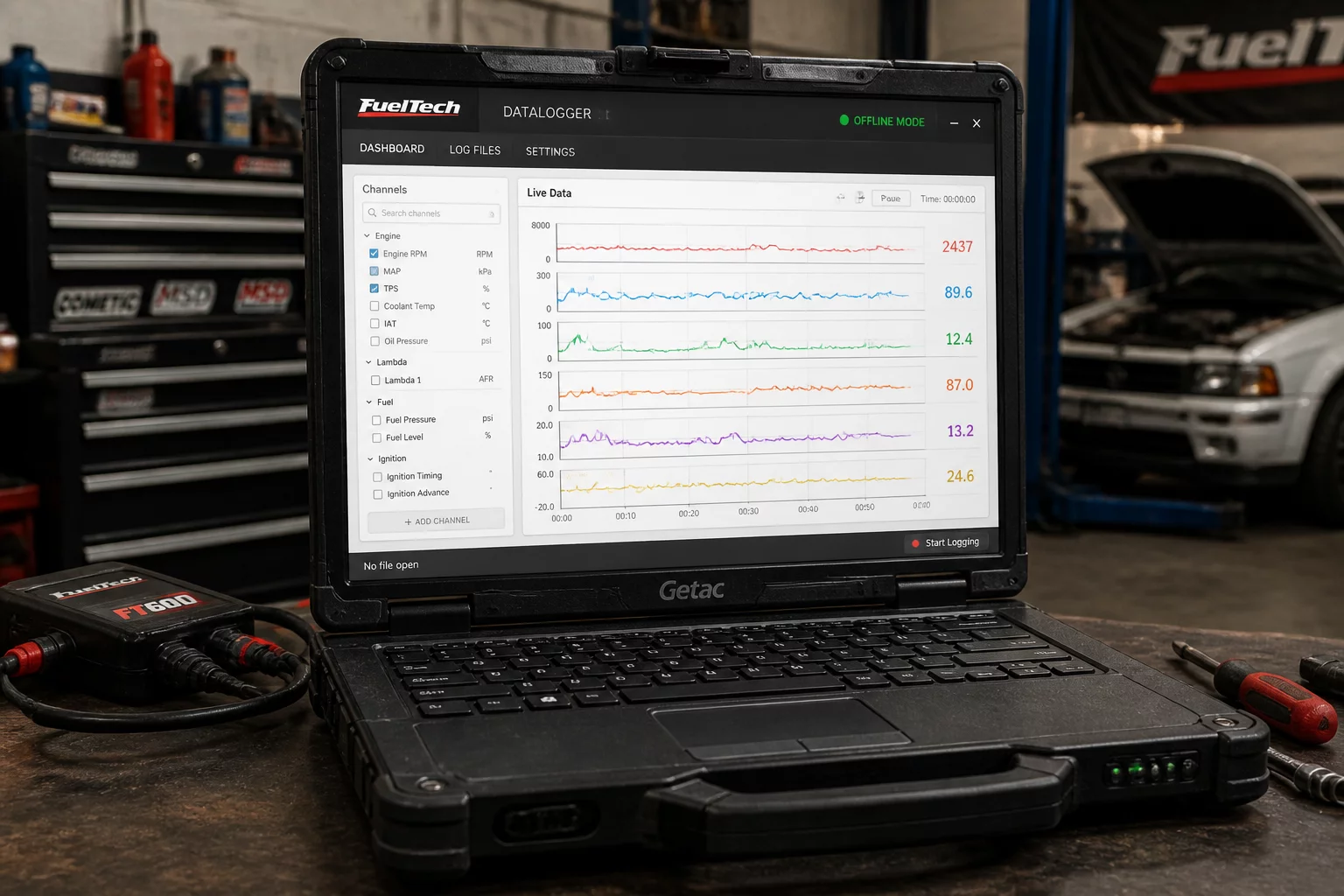
Telemetry capture stability depends heavily on consistent message transmission timing. The 2.3.0 datalogger module introduces an intelligent PID scheduler that dynamically groups single-byte, multi-byte, and UDS extended service queries into synchronized packets. This drastically minimizes bus overhead, allowing up to 64 discrete engine and transmission channels to sample concurrently at rates exceeding 100 Hz.
Achieving sustained 100 Hz polling across 64 channels requires a hardware interface supporting ISO 11898-1 CAN FD and high-speed USB 3.0 or Ethernet communication. Legacy standard CAN 2.0B interfaces will maintain stable operation at throttled rates up to 50 Hz.
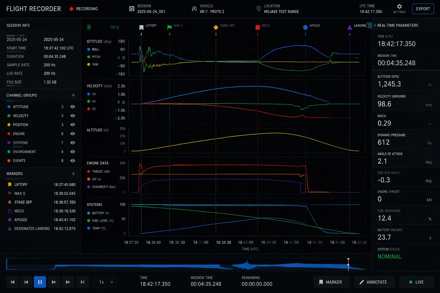
Furthermore, the logging backend now uses an asynchronous circular ring buffer that continuously writes rolling flight records directly to local solid-state storage. Even in the event of sudden bus disconnection or ignition cycling, log data remains intact without index corruption.
Technical Specifications & Bus Metrics
The table below outlines the core diagnostic parameters, sampling capabilities, and protocol specifications verified in the HTS CANBUS 2.3.0 release candidate.
| Parameter | Diagnostic Specification | Verification Standard |
|---|---|---|
| Multi-Channel Polling Rate | 10 Hz – 100 Hz (Hardware dependent) | ISO 14229 / UDS 0x22 |
| Channel Capacity | Up to 64 concurrent PIDs | SAE J1979 / J1979-2 |
| Protocol Compatibility | CAN 2.0B (500 kbps), CAN FD (up to 5 Mbps) | ISO 11898-1:2015 |
| Log Export Formats | .CSV, .MDF4 (ASAM), .LOG | ASAM MDF v4.1.0 |
No comments yet. Be the first to leave a comment.